1
/
of
6
LM1875 Amplifier and Power Supply Board Set (three PCBs, no parts)
LM1875 Amplifier and Power Supply Board Set (three PCBs, no parts)
Regular price
$9.97 USD
Regular price
Sale price
$9.97 USD
Unit price
/
per
Shipping calculated at checkout.
Couldn't load pickup availability
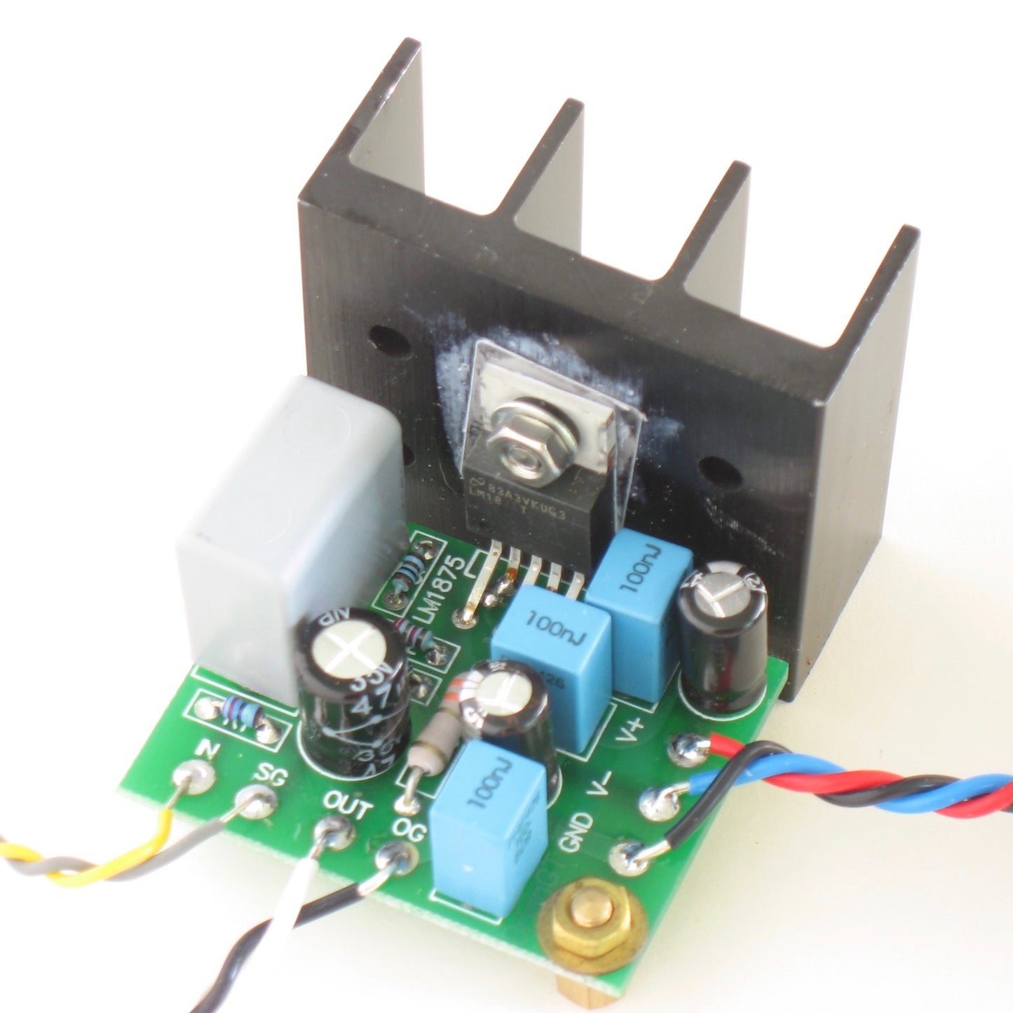
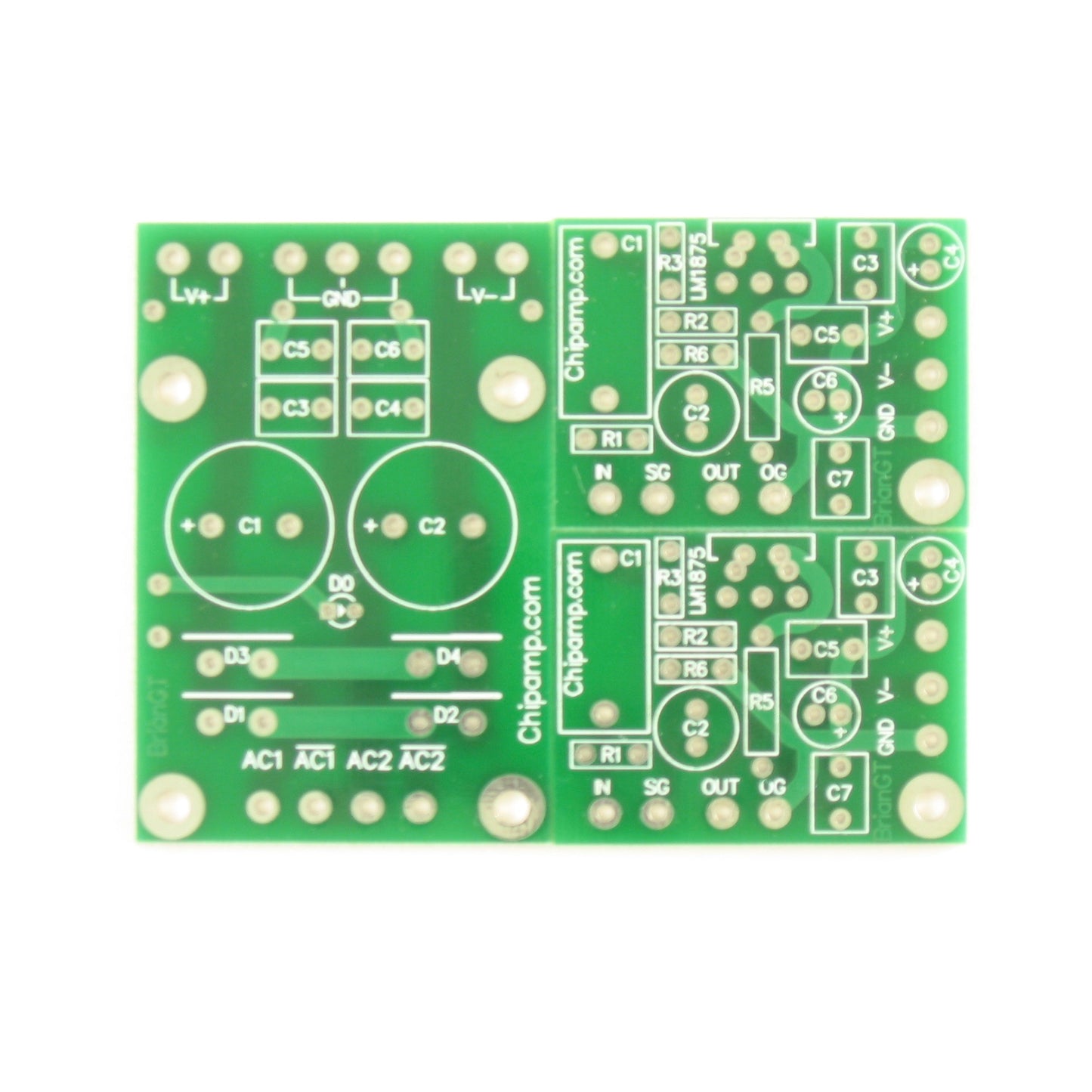
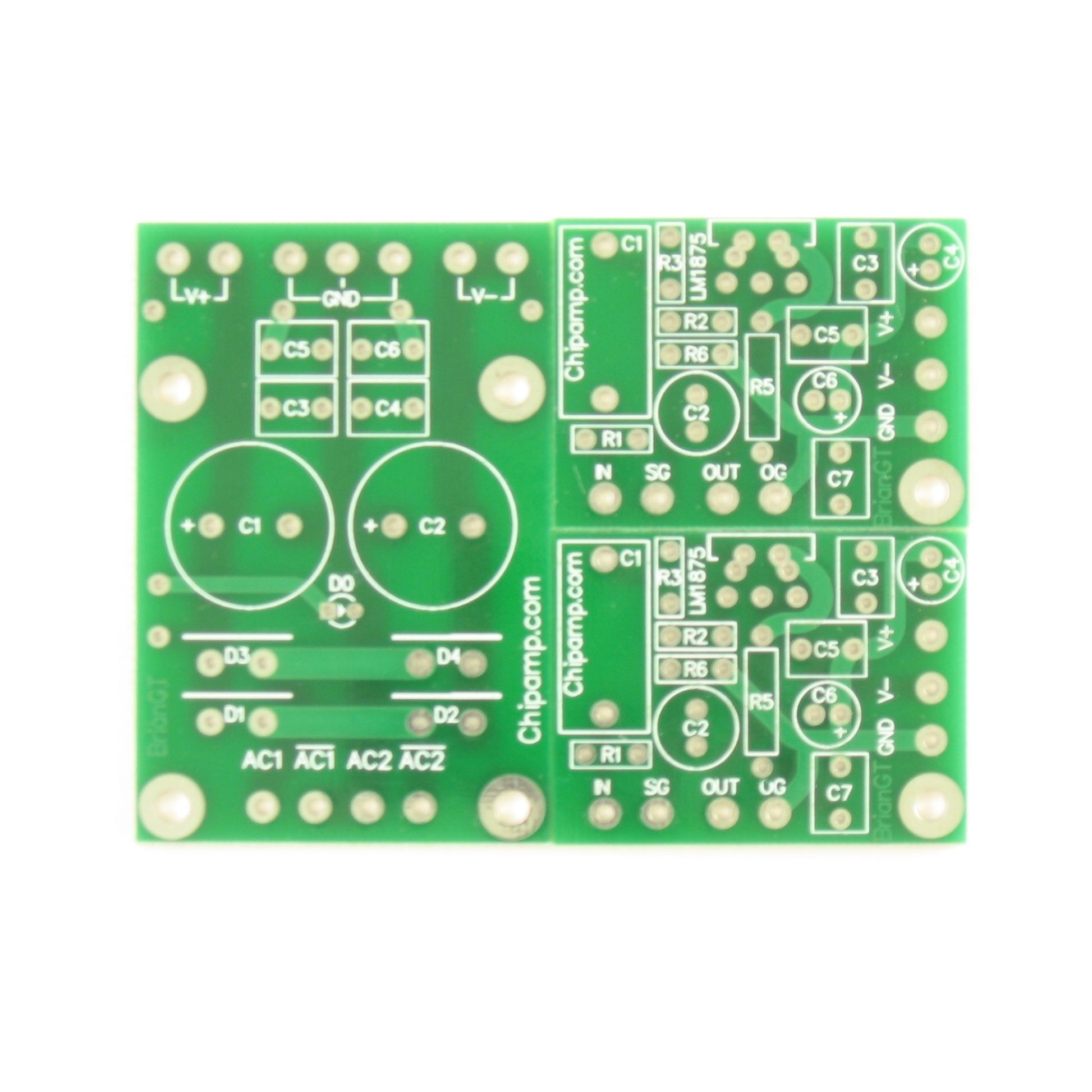
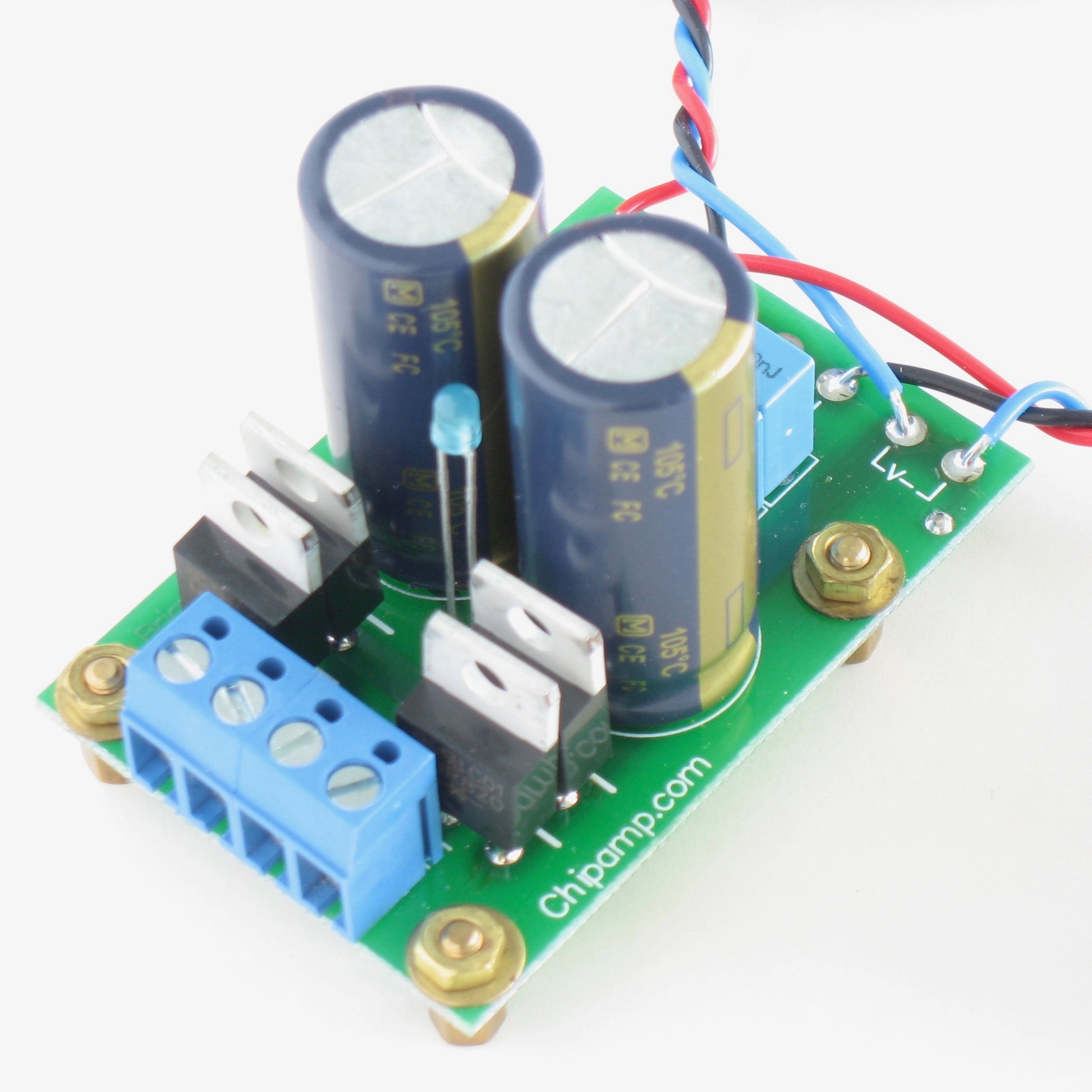
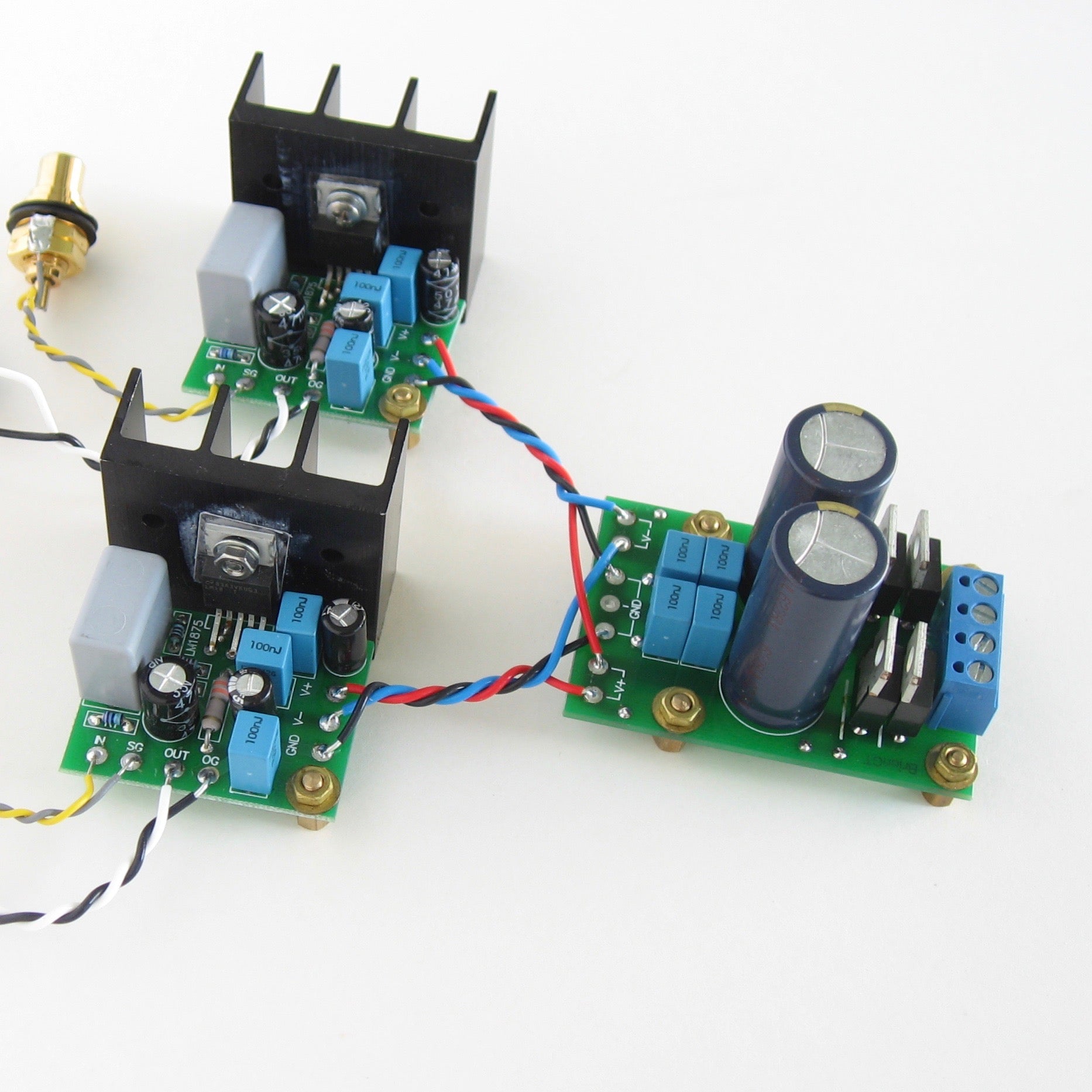
A set of three wonderfully compact PCBs designed by BrianGT for a stereo amplifier based on the LM1875
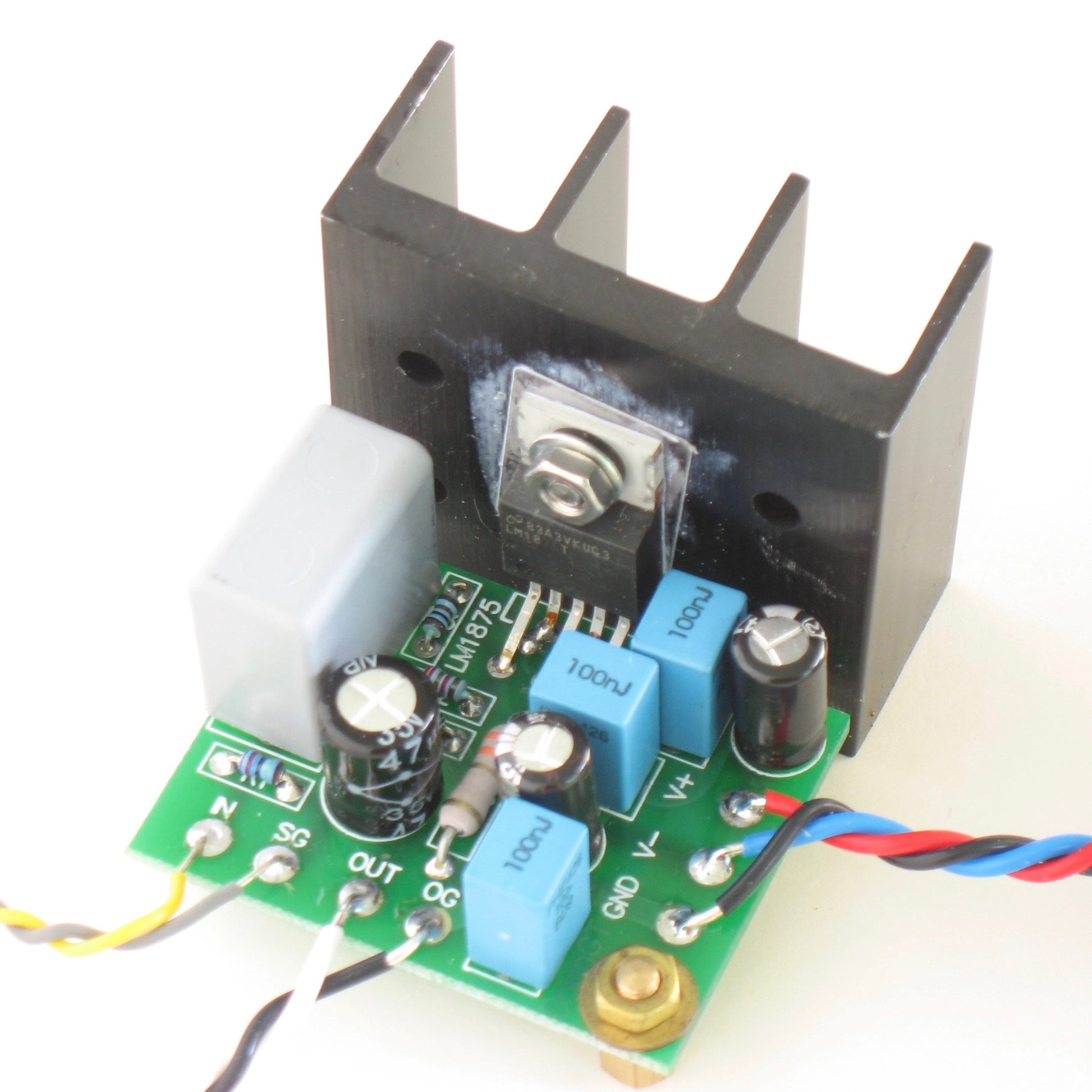
- Minimalist implementation of an LM1875 based audio power amplifier with only a few easy-to-solder through-hole parts
- Designed by BrianGT @ Chipamp.com
- Bare boards only.
- Parts are not included and need to be obtained separately.
- Assembly is required.
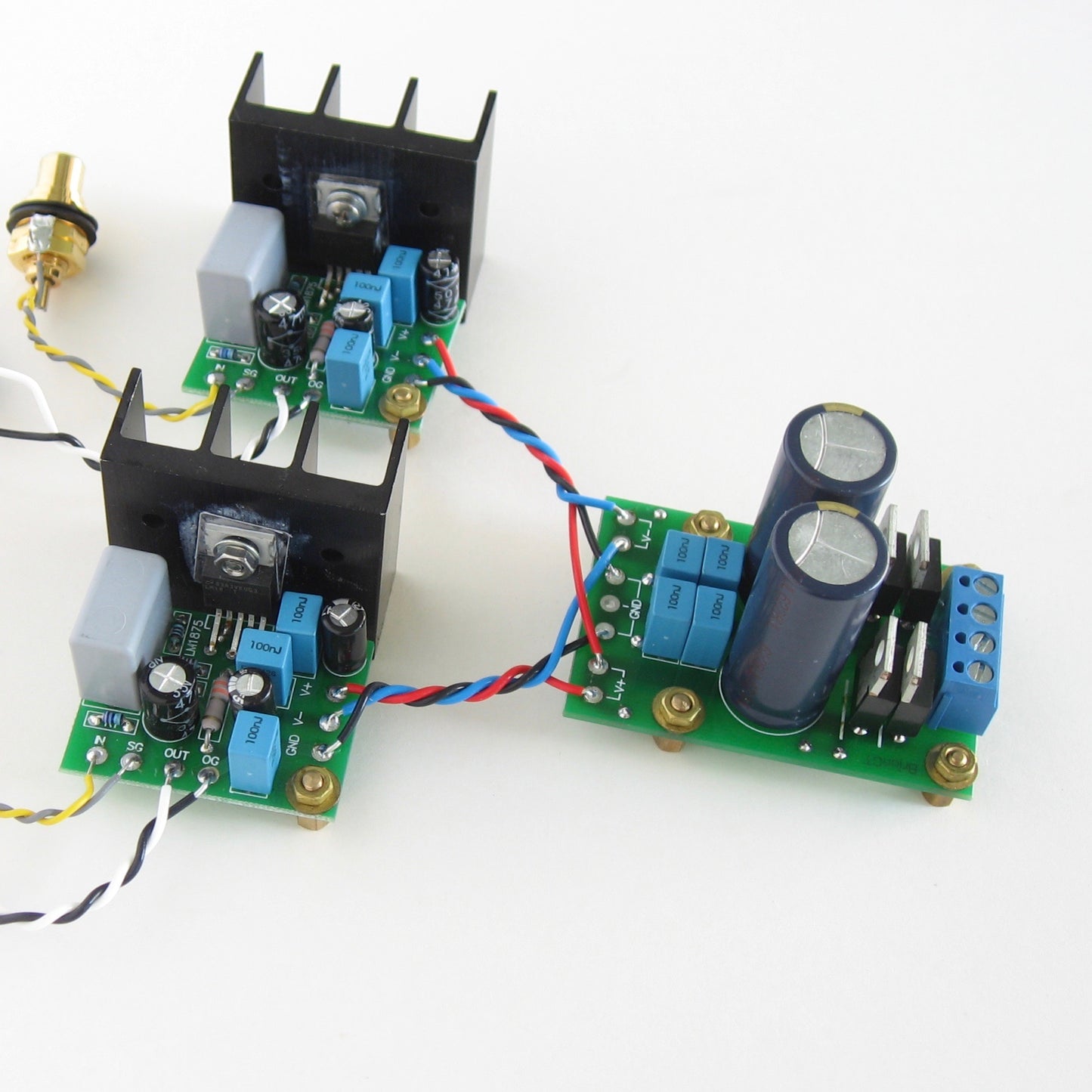
- The set is enough to build a complete stereo power amplifier. (Parts, including suitable power transformer and heatsinks, must be purchased separately.)
- The set includes two amplifier boards (one per channel) and one power supply board.
- Extremely compact boards: amplifier boards are 1.6x1.2in each, power supply board is 1.6x2.4in.
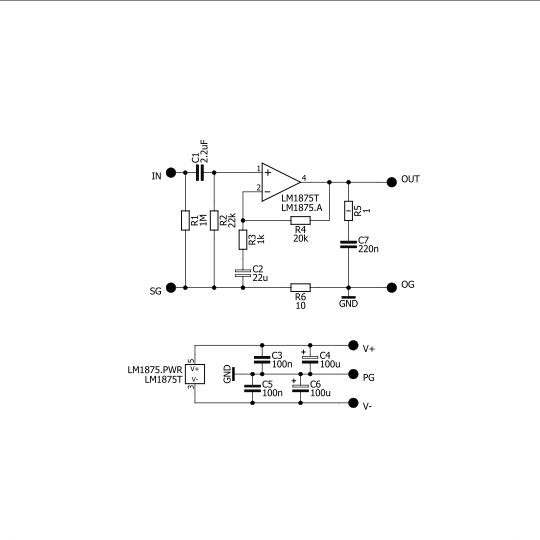
- Each amplifier board implements the standard LM1875 configuration in accordance with the datasheet, plus an optional ground-loop-breaking resistor.
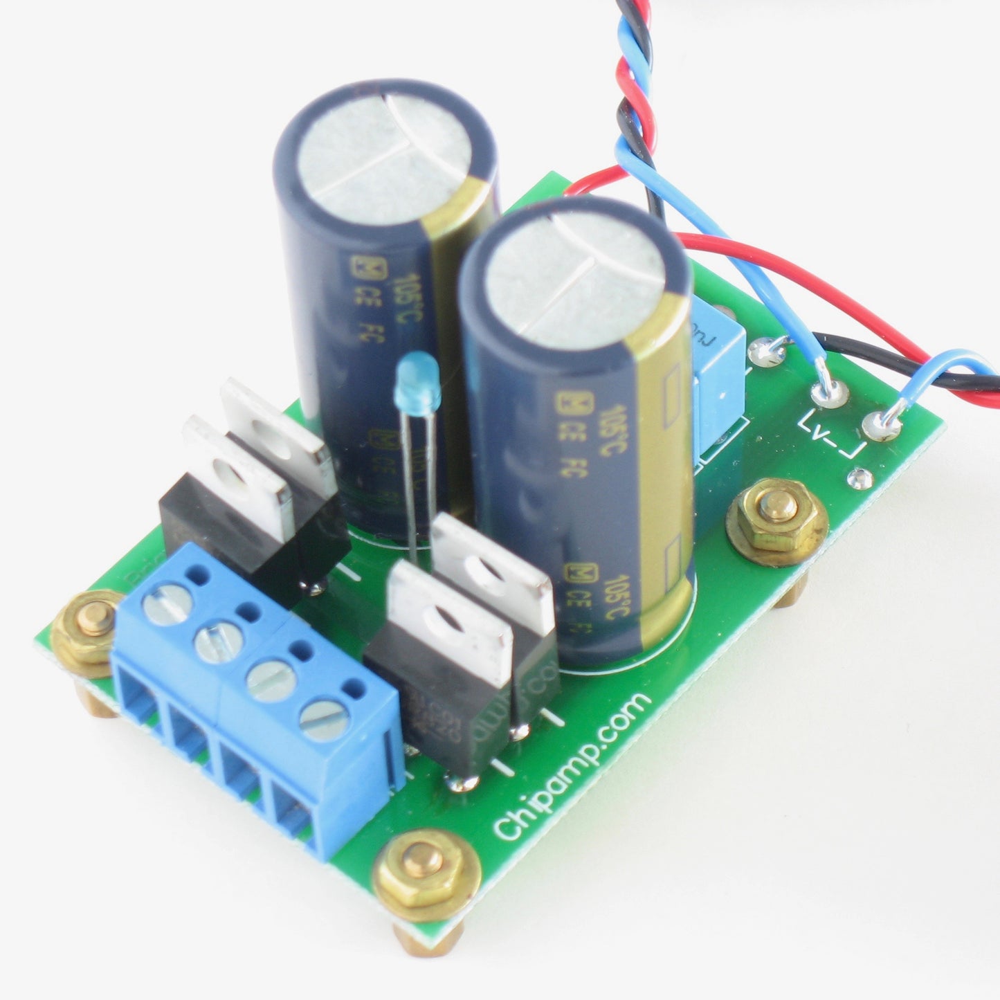
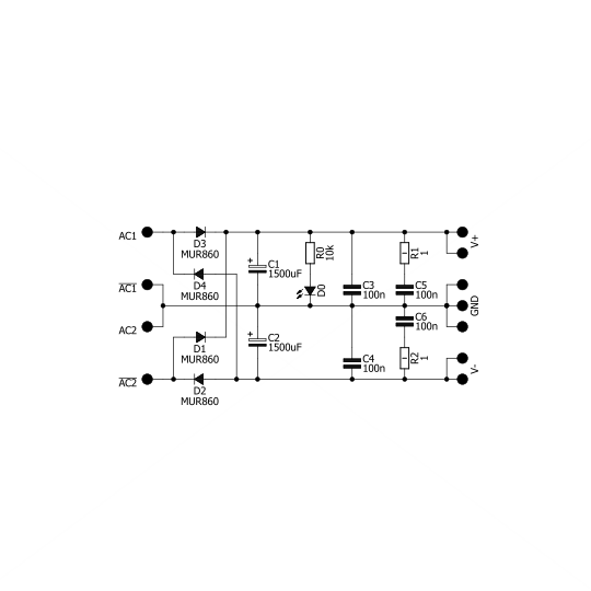
- The power supply board carries a bipolar, unregulated power supply with fast rectifiers such as the MUR8x0 series, CRC snubbers on the DC side and a power-on LED.
- Link to diyAudio.com discussion
Part list for each amplifier board
All resistors except R5 need to be compact metal film type such as Vishay SFR16S. Larger resistors can also be used but will need to be mounted vertically.
- R1 - 1Meg (optional resistor to ground before C1)
- R2 - 20..22k (input to ground resistor)
- R3 - 1k (feedback network resistor, gain = 1 + R4/R3)
- R4 - 20..22k (feedback network resistor, mount on the underside of the PCB)
- R5 - 1ohm 2W, e.g. KOA Speer MOS2 series (zobel network)
- R6 - 10ohm or jumper (optional ground loop breaking resistor)
- C1 - Polypropilene 1 to 2.2µF, 15mm lead spacing, 9mm max width (input capacitor)
- C2 - 22 to 47µF, 35 or 50V bipolar electrolytic, 3.5mm lead spacing, 8mm diameter (feedback network)
- C3 - 0.1µF 50V, 5mm lead spacing, 6mm max width (power supply decoupling)
- C4 - 47 to 100µF, 35 or 50V electrolytic, 6.3mm diameter, 2.5mm lead spacing (power supply decoupling)
- C5 - 0.1µF 50V, 5mm lead spacing, 6mm max width (power supply decoupling)
- C6 - 47 to 100µF, 35 or 50V electrolytic, 6.3mm diameter, 2.5mm lead spacing (power supply decoupling)
- C7 - 0.22µF 50V, 5mm lead spacing, 6mm max width (zobel network)
Part list for power supply board
- R0 - 10k compact metal film type such as Vishay SFR16S (series resistor for LED)
- R1,R2 - 1ohm 2W such as KOA Speer MOS2 (optional "snubber" network resistors, mount on the underside of the PCB)
- C1,C2 - 1500µF 35 to 50V, 16mm diameter (main power supply caps)
- C3,C4 - 0.1µF 50V, 5mm lead spacing, 6mm max width (power supply decoupling)
- C5,C6 - 0.1µF 50V, 5mm lead spacing, 6mm max width (optional "snubber" network capacitors)
- D0 - LED (power-on indicator)
- D1-D4 - MUR860 rectifier diodes
Share
